Links
Good tracks to listen
Worakls - Stephan Bodzin - Ben Böhmer - Colyn - Sainte Vie | Melodic Techno Classics mix 2016 / 2019
2RAUMWOHNUNG - Wir werden sehen (Paul Kalkbrenner Remix) 'Lasso Remixe'
English
https://jestineyong.com/how-to-repair-amplifier-no-sound/
https://jestineyong.com/about-shorted-transistor/
https://audiokarma.org/forums/index.php?threads/blowing-a-power-transistor-root-cause.196876/
https://www.thegearpage.net/board/index.php?threads/what-causes-power-transistors-to-fail-solid-state-amps.945586/
French
https://www.pascalchour.fr/ressources/repar_ampli/repar_ampli.htm
http://jeanluc.rigal.free.fr/reparer_un_ampli_hi-fi.html
http://www.bedwani.ch/electro/ch14/index.htm
Réparation canal droit РОМАНТИКА 15у-120
Russian
https://forum.cxem.net/index.php?/topic/74746-романтика-15-120-с-hi-fi/
https://forum.cxem.net/index.php?/topic/117997-романтика-15-120-с-hi-fi-не-работает/
http://radiostorage.net/3225-usilitel-romantika-15u-120-50u-220-stereo.html
Методика ремонта транзисторного УМЗЧ - Аудиоаппаратура - Форум по радиоэлектронике
Files: Original RU or automatic translation EN
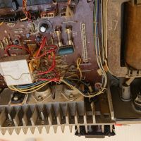
What happened
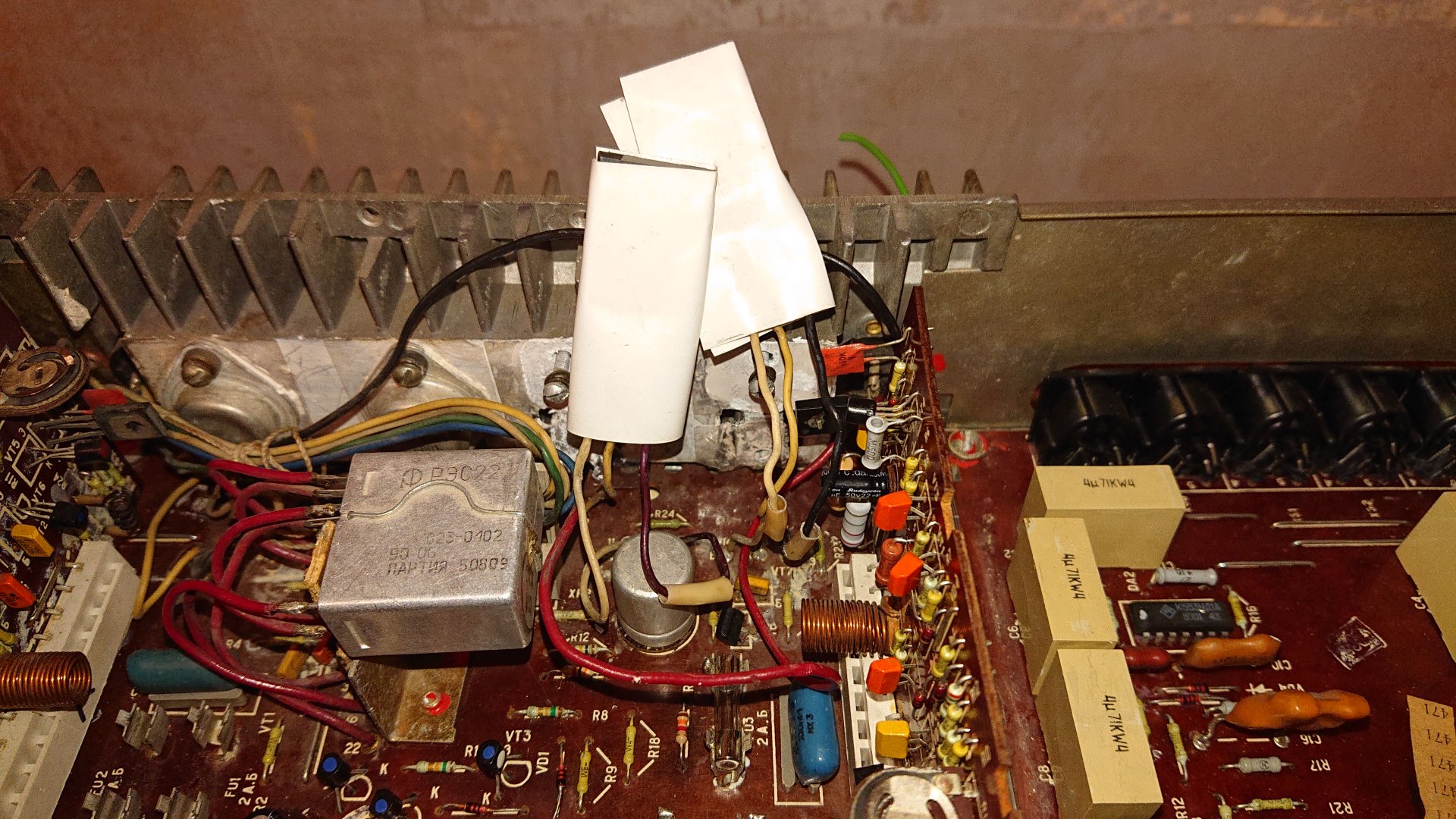
The amplifier is a Романтика 15-120С. It sounds quiet nice but sometime the sound gets no so clear either on right or left speaker.
To fast improve sound quality, I unpluged and replugged AUX input 3.5 jack. Dumb but done. One day it resulted on no more sound at all.
I quickly found dead fuse F3. I took one of the fuse of the other channel and F3 died again. Dumb but done.
I put 2 working fuse on left channel, and 2 dead fuse on right channel. Switched on the amplifier. Left channel is working. Good.
After reading internet, I quickly suspected that power transistor of the right channel were shorted. It was the case.
Test a transistor

How to test a TRANSISTOR with a multimeter PNP or NPN
How to check fuses, diodes, transistors, voltage regulators
3 Ways to Check Capacitors in Circuit with Meters & Testers
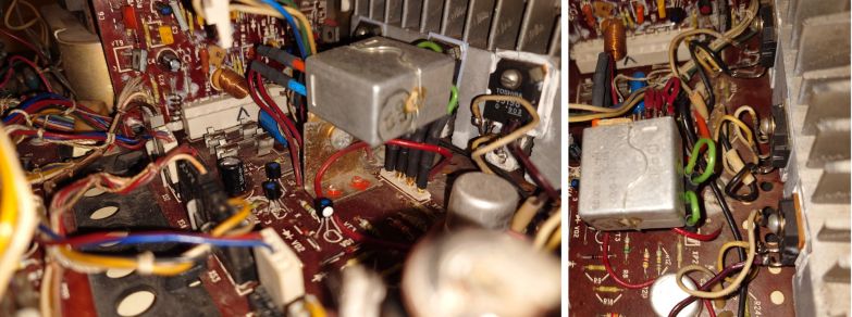
Troubleshooting (eyes+multimeter)
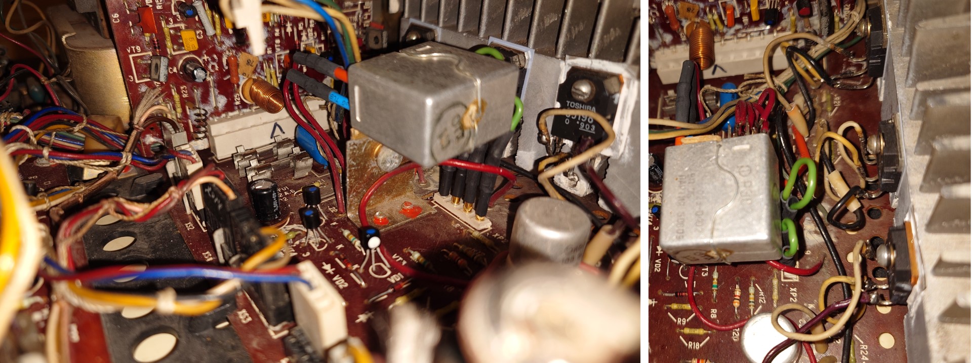
Le fusible FU3 de l'alim +27V cramé.
Les deux transistors de puissance VT3 et VT4 en cours-circuit.
=> +27V s'est vidé en quasi direct dans le -27V (R23 et R24 de 0.22ohm sur le chemin)
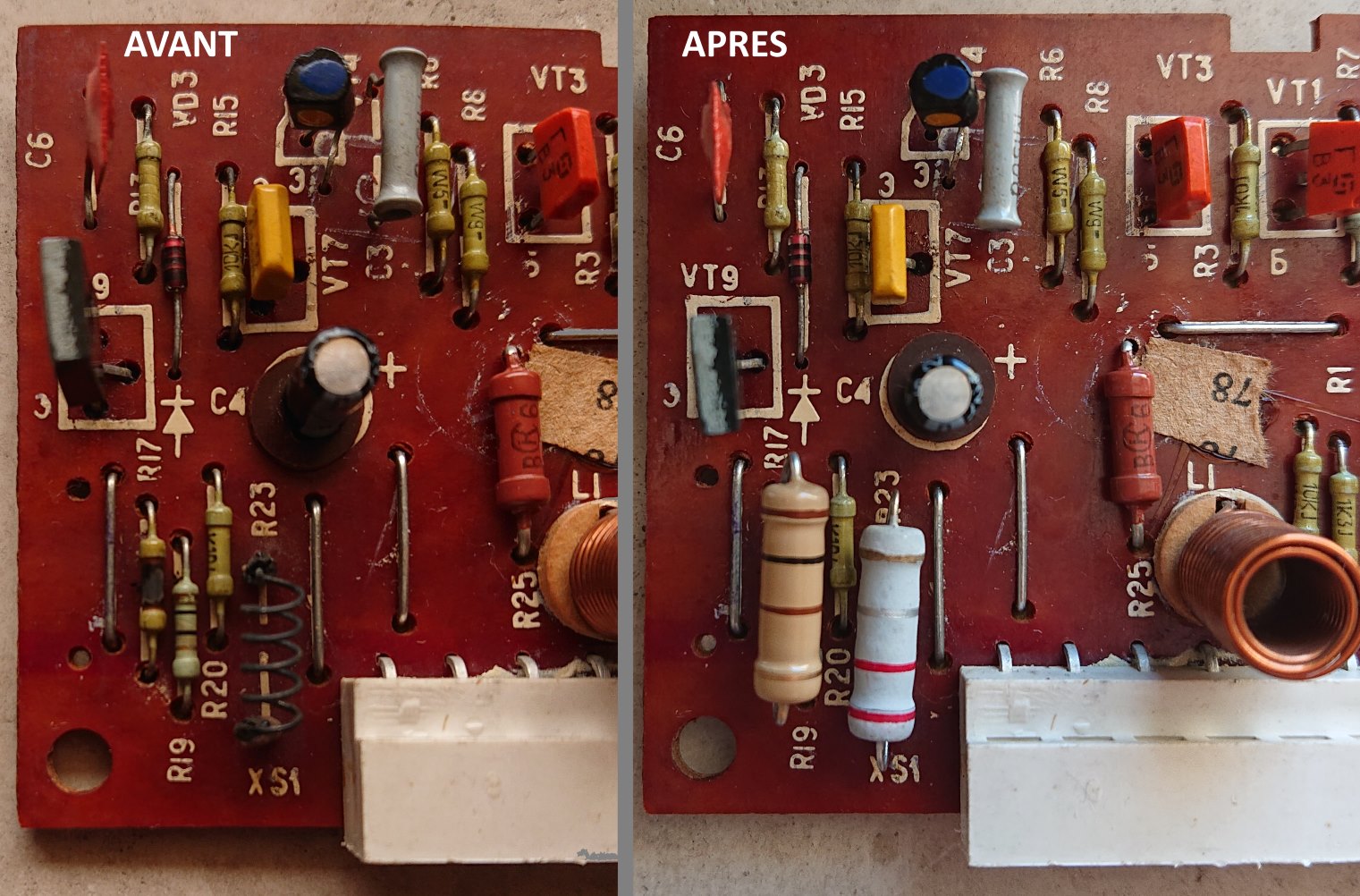
R15 et R20 cramées sur la carte principale.
R17 et R23 cramées sur la carte module de la voie droite.

Power transistors that were in service before the problem
Left channel (working), original ones:
Right channel (not working), not original ones:
Intervention
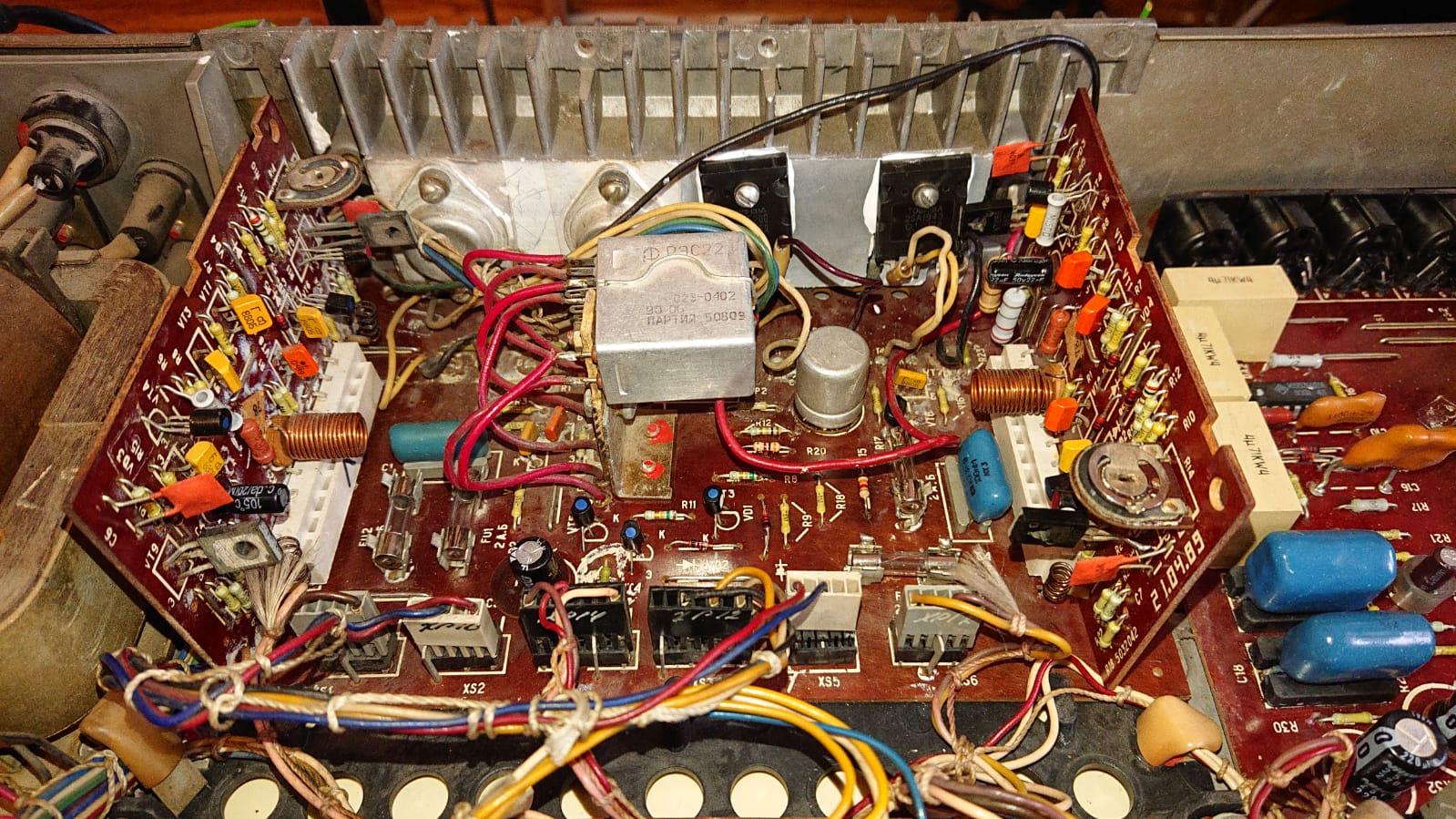
Remplacement des transistors
PNP A1941 => A1943
NPN C5198 => C5200
Les nouveaux sont un peu plus gros. Il me reste à les coller sur le radiateur (je n'ai pas pu reprendre les anciens mica).
Remplacement des résistances sur la carte principale
R15 et R20. J'ai mis des 1/4W en comparant visuellement...
Ces résistances servent à prévenir l'utilisateur qu'un certain niveau de puissance a été atteint à travers l'alimentation d'une LED.
Remplacement des résistance sur la carte module
R17 100 ohm je voulais mettre 1/4W mais le vendeur n'avait plus que du 2W.
R23 0.22 ohm. A la base la résistance avait une forme de ressort (j'imagine que ces résistance doivent avoir une petit propriété inductive ?). Le vendeur n'en avait pas. J'ai hésité entre 2W et 5W. J'ai mis une 2W de forme classique.
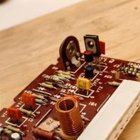
Power transistor replacing broken ones
Fixed!
Intervention 2 - January 2024
After first intervention the amplifier worked well for a while and then start to be unstable, with too much cracks on the right channel
It was then replaced by a small chinese amplifier. Романтика 15-120С remained unused for about 3 years.
Then troubleshooting occured again in December 2023:
- By swapping the the amplifier module boards, it was identified that the defective(s) componant(s) where on the module board.
- Using multi-meter, VD1 was found faulty and replaced (but installed in the wrong way!).
Amplifier worked well for a day then started again to crack and even relay protection was triggered every few seconds due to this same right canal.
- Comparing right and left modules using multimeter to measure each resistance and diode showed something different around VD1 VD2.
- VD1 was put in the right way.
So far so good.
Intervention 3 - March 2024
Online Tone Generator - Free, Simple and Easy to Use.
The right speaker is working always good after intervention 2. But sometimes, the left channel is obvioulsy producing a lighter sound. I would say it is the case since I bought it.
By swapping the channels output from preamplifier, problem did not moved to the other side.
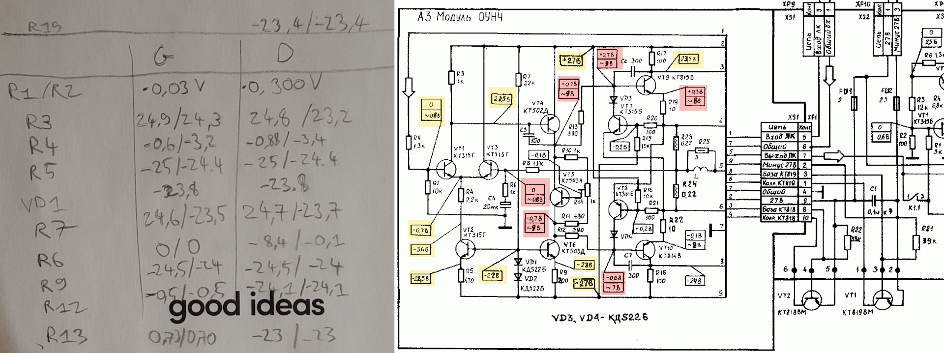
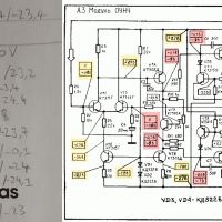
But for some reasons I checked preamplifier voltages vs. what is written on the schema:

I then swapped VT1 and VT2. The voltage values from left channel (top on the schema) exchanged with right chanel (bottom).
It didn't solve the problem but I will try to find a КП303Е transistor to get voltage in line with schematic (or not because sound is good anyway).
- КП303Е: аналог
D - drain (сток)
S - source (исток)
G - gate (затвор)
- Транзистор полевой КП303 - DataSheet
- 2П303А, 2П303Б, 2П303В, 2П303Г, 2П303Д, 2П303Е, 2П303И, КП303А, КП303Б, КП303В, КП303Г, КП303Д, КП303Е, кКП303Ж, КП303И - Транзисторы кремниевые эпитаксиально-планарные полевые с затвором на основе p-n перехода и каналом n-тила - 2p303_kp303.pdf
- 2N5459R Datasheet Search
Sumup of operations:
- I swapped right and left chanel at several location:
- Before the preamplifier
- After the preamplifier / Before the amplifier
- I swapped КП303Е transistor (VT1 and VT2 on preamplifier board)
- I swapped right and left channel модуль ОУНЧ
- I swapped speakers
Problem always remained on the left channel.
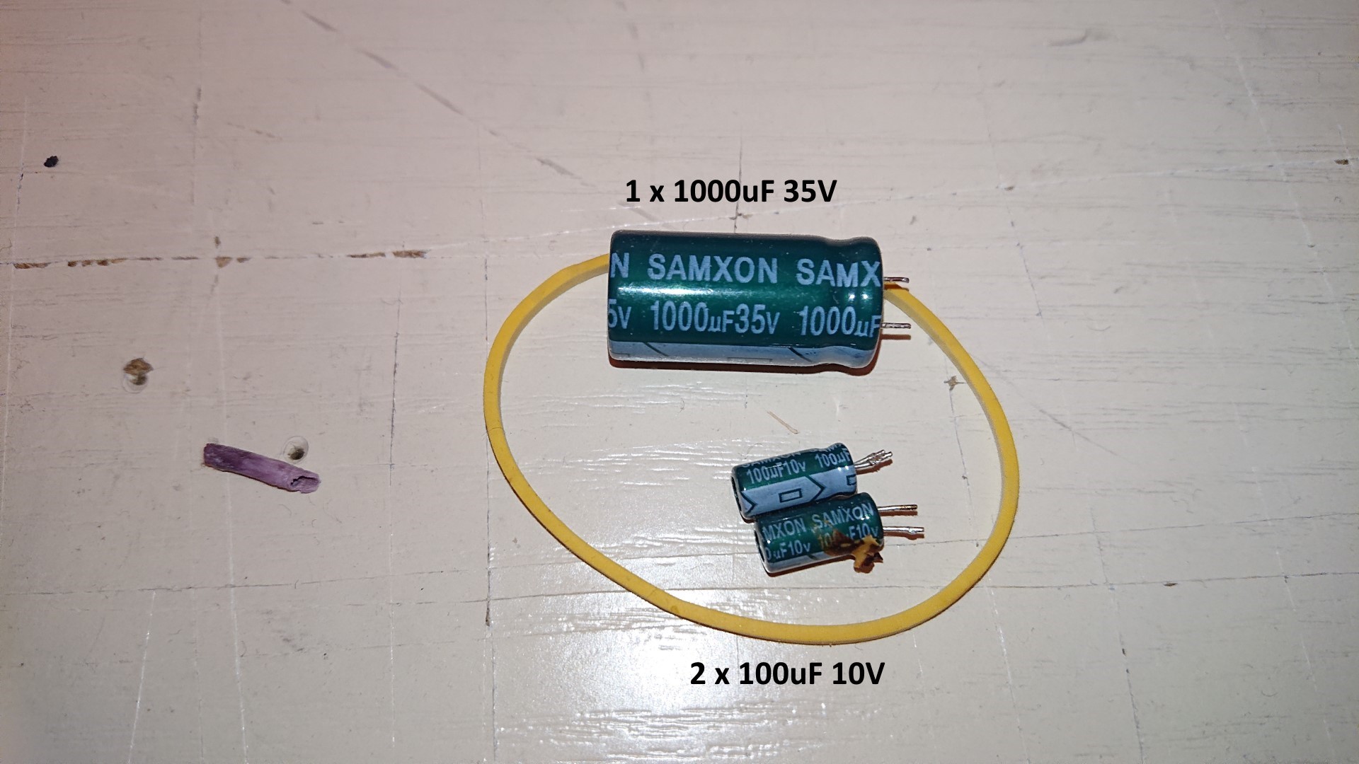
Conclusion: it is due to some component on the last stage. Obvious old component : two power amplifier transistors and on old capacitor which is not on the way of the sound signals. Replaced.


Now need to listen music!
Intervention 4 - July 2024
So, intervention 3 didn't solve the issue with left channel to sometimes loosing sounds and strange noise when playing very low frequencies.
My conclusion above was : it is due to some component on the last stage.
So studying the schematics again I checked what it could be:
- Relay
- C1 capacitor
- Resistor R21 and R22
I changed the relay. Not better.
I swapped C1 with C4 of the right channel. Not better.
I was disapointed and checked again the schematic. Then I saw the signal was going to the headphones plug before going to speakers. I decided it won't go there anymore: I disconnected XP2 and put small jumpers (below in green).
So far so good. One bonus difference I noticed, phones frequency are not audible anymore (before a call or when receiving a SMS). Now need to listen music!
21/09/2024 : still very nice sound. So nice to listen to music.
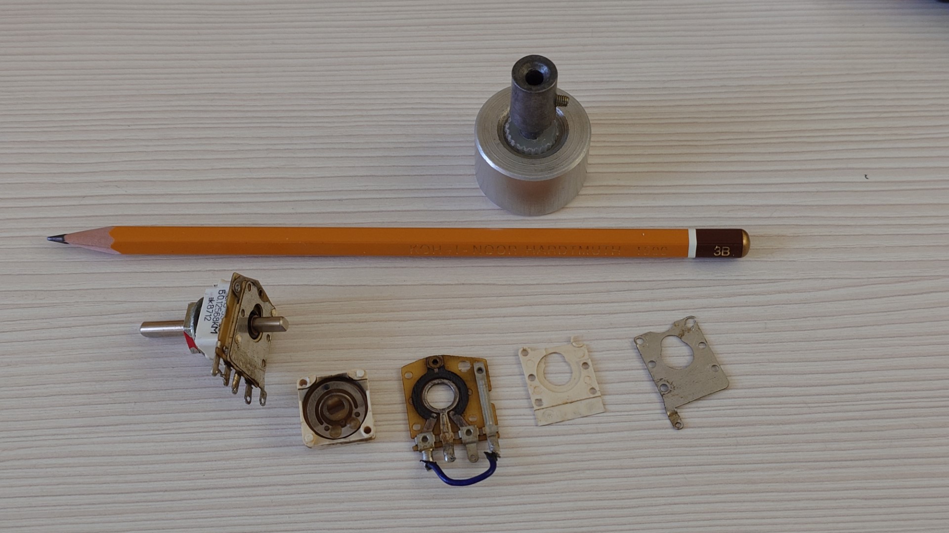
Intervention 5 - September 2024 : fixing balance potentiometer СП3-33-22 68к
This balance potentiometer is shunted since months. On the left channel it was hard to keep the signal.
So I removed it, opened it, cleaned it, and I used a 3B pencil to apply graphit on its track. See link above for illustration.

27/01/2025: above intervention it did not help more than a couple of days. I shunted the balance potentiometer.
Intervention 6 : January 2025 : fixing right channel
Same simptoms that leaded to intervention 2 accored again on right channel. Worked for a small time then relay was protecting the speaker from DC voltage.
Swaping ОЧНУ modules between channels put in evidence that the probem was on right channel ОЧНУ plate.
I measured voltages on both boards and indeed there was a DC voltage on the output.
I thought measuring the votages and compare could help me identify which component was faulty. So i read a bit more a watched few videos:
Well, it didn't help. I changed my mind: I will swap component by component starting with the ones specified in this video
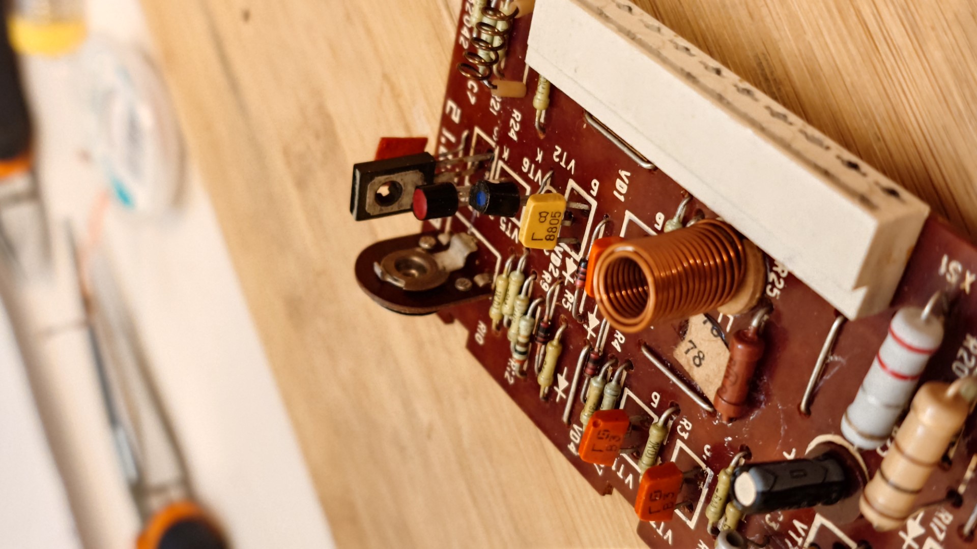
Well, I swapped component after component and testing each time the faulty board:
- VD1 + VD2 because it was the rootcause of similar symptoms problem fixed by intervention 2
- C4 because chemical capacitors
- VT2 because near VD1 + VD2 diodes
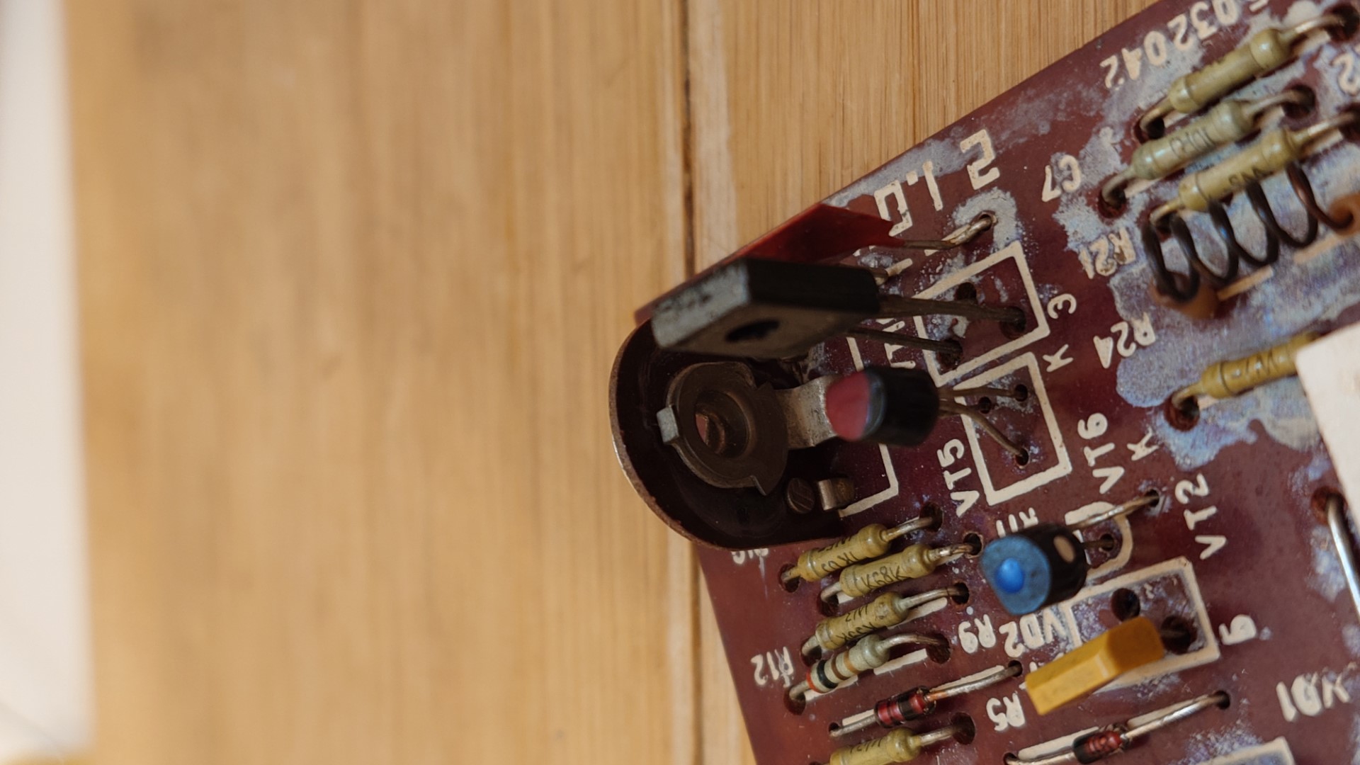
- VT5 bias transitor as mentionned in above video
- VT1+VT3 because differencial pair as mentionned in above video from 2min20
After which I found the -150mV at ОЧНУ signal input of left channel board (reference) and -30mA at ОЧНУ input of right channel board. Which was the opposite before swaping.
I notice at this moment that radiator was much hotter than usual. I had to adjust the bias of the reference board.
- VT6 because near VD1 + VD2 diodes
From here, both channel are working very well. So I suppose there was (were) some dry solder(s).
Again the radiator was getting much hotter than usual. So I adjusted the bias of the previousy faulty board of right channel.
Bias adjustment
First four messages helped me doing this: Help, how to adjust trimer(potentiometer) on transistor amplifier
While they speak about 50mA I aways heard 20mA or less. I targetted 20mA first then even less because I did not hear any differences.
What I did:
- Using volltmeter in DC, I measured the voltage at R23 or R24 (0.22 ohm/5W output resistors)
- I found 120mV which means U = RI => I = U/R => I = 0.120/0.22 = 545mA !!!! Of course radiator got hot.
- 20mA target means U = RI = 0.22 x 0.20 = 4.4 mV
- Using R14 I adjusted the voltage at R23/R24 to be less than 4.4 mV.
Intervention 7 : February 2025 : fixing left channel
Everything was working very nicely until 02/02/2025. Then left channel stoped working. When swapping the ОЧНУ modules, the problem was going to the other channel. Problem is on ОЧНУ.
Well, I restarted swapping ОЧНУ component after component and testing each time the faulty board:
- VT4 because same stage than VT6
Swapping VT4, the problem followed VT4. Need to find a КТ502Д transistor.
I couldn't find a КТ502Д but I could find a КТ502Е.
05/02/25 VT4 replaced by a КТ502Е showed that the output was stabled (no more DC voltage) but the sound is not clear.
I bough some КТ502Д transistors online. Need to wait for them.
24/02/25 I installed a КТ502Д for VT4 but same behavior than with a КТ502Е... I kept the КТ502Е installed.
Well, I restarted swapping ОЧНУ component after component and testing each time the faulty board:
- VT7 not better
- VT8 not better
- VT9 fixed!!
Swapping VT9 + soldering VT9 very carefully because on the unclear sound channel board, the tracks where VT9 is soldered are unsticked (!) and one track continuity is even brocken. I fixed the track by using a fair amount of solder.
Now listening again nice quality sound while waiting for the next problem !
In the futur : to make new PCB or use chinese made amplifier boards
https://www.pcbway.com/
Maybe i could use stuff like this to repair last stage: Amplifier Board - AIYIMA A2D847